Analysing gyroscope's motion
Construction of gyroscope
A gyroscope consists of a rotor that is fixed to a gimbal. The rotor and the gimbal are free to rotate along axes that are particular to each other. A base supports the gimbal-rotor system. As the gimbal and rotor rotate, the base precesses about the vertical axis.
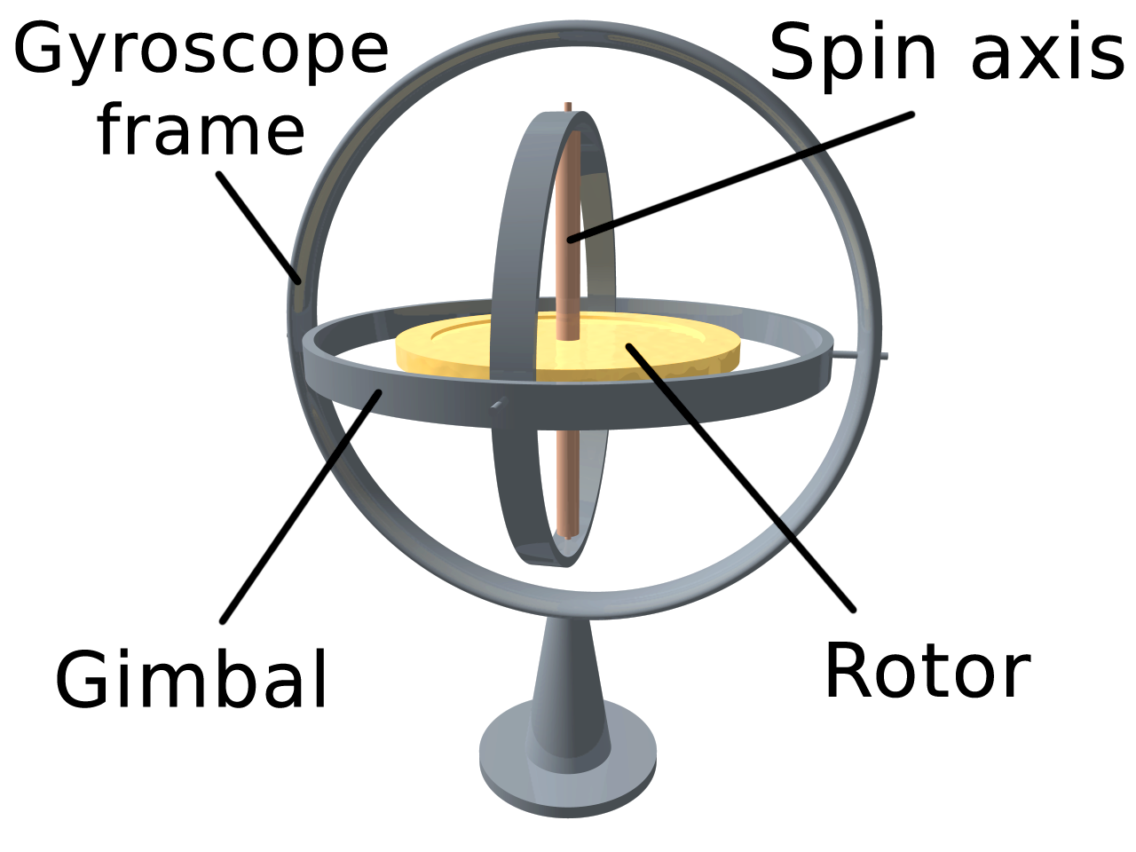
(By No machine-readable author provided. LucasVB assumed (based on copyright claims). - No machine-readable source provided. Own work assumed (based on copyright claims)., Public Domain, Link)
Defining frames of reference
To understand the dynamics of a gyroscope, it’s useful to use two frames of reference. One is an inertial frame with origin at the center of the rotor. This is a fixed frame and doesn’t move with any part of the gyroscope. The inertial frame is defined by \(XYZ\). The other frame is a non-inertial frame that is attached to the gimbal and hence moves with the gimbal. \(\mathbf{\hat{I}}\), \(\mathbf{\hat{J}}\), and \(\mathbf{\hat{K}}\) are the unit vectors along \(X\), \(Y\), and \(K\) directions respectively. \(\mathbf{\hat{i}}\), \(\mathbf{\hat{j}}\), and \(\mathbf{\hat{k}}\) are the unit vectors along \(x\), \(y\), and \(z\) directions.
When the rotor spins, the base, and hence the entire gyroscope assembly, precess around the \(+Z-\) axis of the \(XYZ\) frame at a constant angular velocity \(N\). The orientation of the \(xyz\) frame relative to \(XYZ\) frame is shown in figure below. Since \(xyz\) frame keeps moving relative to \(XYZ\) frame, the figure captures the orientation at a particular at a particular instant. At the instant shown, the \(x-\) axis coincides with the \(Y-\) axis, \(z-\) axis makes an angle \(\theta\) with the \(Z-\) axis of the \(XYZ\) frame, and the origins of both the frames coincide.

The rotor spins about the \(z-\) axis with a constant angular velocity
\(\omega_{\text{spin}}\). The gimbal rotates about the \(x-\) axis with a constant
angular velocity \(\dot{\theta}\) relative to the \(Z-\) axis. When \(\theta = 0\),
the rotor is parallen to the ground and the gimbal is perpendocular to the ground;
\(z-\) axis coincides with \(Z-\) axis, and \(y-\) axis coincides with the
negative \(X-\) axis.
Analysis of gyroscopic motion
We want to find the angular velocity of the rotor relative to the \(XYZ\) frame. We also want to express the angular velocity vector in both \(xyz\) and \(XYZ\) frames of reference.
The angular velocity of the rotor relative to the \(XYZ\) frame is given by the following expression:
\[\begin{equation} \left( \begin{array}{c} \text{Angular velocity} \\ \text{of the rotor} \\ \text{relative to} \\ \text{XYZ frame} \\ \end{array} \right) = % \left( \begin{array}{c} \text{Angular velocity} \\ \text{of the rotor} \\ \text{relative to} \\ \text{gimbal} \\ \end{array} \right) + % \left( \begin{array}{c} \text{Net angular} \\ \text{velocity of the} \\ \text{gimbal relative} \\ \text{to XYZ frame} \end{array} \right) \end{equation} \label{eq:one}\]We know the first term on the right hand side, but the second term is unknown. In fact, the second term is the resultant of angular velocity vector of the gimbal and the angular velocity vector of the base. Here both the vectors are measured relative to the \(XYZ\) frame.
\[\begin{equation} \left( \begin{array}{c} \text{Net angular} \\ \text{velocity of the} \\ \text{gimbal relative} \\ \text{to XYZ frame} \end{array} \right) = % \left( \begin{array}{c} \text{Angular velocity} \\ \text{of the gimbal} \\ \text{relative to} \\ \text{XYZ frame} \end{array} \right) + % \left( \begin{array}{c} \text{Angular velocity} \\ \text{of the base} \\ \text{relative to} \\ \text{XYZ frame} \end{array} \right) \end{equation}\] \[\begin{equation} \mathbf{\omega_{\text{gimbal}}} = \dot{\theta}\, \mathbf{\hat{i}} + N\, \mathbf{\hat{K}} \end{equation} \label{eq:angvel-gimbal}\]The vectors in the above expression can not be added because they are represented in two different frames of reference. However, they can be added if \(N\, \mathbf{\hat{K}}\) is represented in the \(xyz\) frame. The corresponding vector in the \(XYZ\) frame can be obtained by the following expression:
\[\begin{equation} \begin{pmatrix} \mathbf{\hat{I}} \\ \mathbf{\hat{J}} \\ \mathbf{\hat{K}} \end{pmatrix} = % \begin{bmatrix} 0 & -\cos\, \theta & \sin\, \theta \\ 1 & 0 & 0 \\ 0 & \sin\,\theta & \cos\, \theta \end{bmatrix} % \begin{pmatrix} \mathbf{\hat{i}} \\ \mathbf{\hat{j}} \\ \mathbf{\hat{k}} \end{pmatrix}. \end{equation} \label{eq:t-matrix}\]where the \(3 \times 3\) matrix on the right hand side is called the transformation matrix. From \eqref{eq:t-matrix}, it is clear that
\[\begin{equation} \mathbf{\hat{K}} = \sin\, \theta\, \mathbf{\hat{j}} + \cos\, \theta\, \mathbf{\hat{k}}. \end{equation} \label{eq:K-eqn}\]Substituting equation \eqref{eq:K-eqn} into equation \eqref{eq:angvel-gimbal}, we get,
\[\begin{equation} \mathbf{\omega_{gimbal}} = \dot{\theta} \mathbf{\hat{i}} + N \sin\, \theta\, \mathbf{\hat{j}} + N \cos\, \theta\, \mathbf{\hat{k}} \end{equation} \label{eq:angvel-gimbal-xyz}\]Substituting equation \label{eq:angvel-gimbal-xyz} into equation \label{eq:one}, we get,
\[\begin{equation} \boxed{ \mathbf{\omega_{rotor}} = \dot{\theta} \mathbf{\hat{i}} + N \sin\, \theta\, \mathbf{\hat{j}} + (N \cos\, \theta\, + \omega_{\text{spin}})\, \mathbf{\hat{k}} } \end{equation} \label{eq:angvel-rotor-xyz}\]Equation \eqref{eq:angvel-rotor-xyz} provides the components of the angular velocity of the rotor relative to the inertial frame and represented in the \(xyz\) frame. The same vector can be expressed in the \(XYZ\) frame using the transformation matrix given in equation \eqref{eq:t-matrix}.
\[\begin{equation} \begin{pmatrix} \mathbf{\omega_{X}} \\ \mathbf{\omega_{Y}} \\ \mathbf{\omega_{Z}} \end{pmatrix} = % \begin{bmatrix} 0 & -\cos\, \theta & \sin\, \theta \\ 1 & 0 & 0 \\ 0 & \sin\,\theta & \cos\, \theta \end{bmatrix} % \begin{pmatrix} \dot\theta \\ N \sin\, \theta \\ N \cos\, \theta + \omega_{\text{spin}} \end{pmatrix} \end{equation}\]Simplifying this yields the components of the angular velocity vector relative to and expressed in \(XYZ\) frame. This expression holds good only for the instant shown – the instant at which \(x\) and \(Y\) axes and the origins of the frames coincide. This is because the transformation matrix is derived for this instant and it would be different for any other instant.
\[\begin{equation} \boxed{ \mathbf{\omega_{rotor}} = \omega_{\text{spin}}\, \sin\, \theta\,\mathbf{\hat{I}} + \dot{\theta}\,\mathbf{\hat{J}} + \left(N + \omega_{\text{spin}}\, \cos\, \theta\, \right) \mathbf{\hat{K}} } \end{equation}\]Angular acceleration of the rotor
Angular acceleration is the time derivative of angular velocity. We want to find angular acceleration vector relative to \(XYZ\) frame and express that vector in both \(xyz\) and \(XYZ\) frames.
\(xyz\) frame is rotating with an angular velocity
\[\begin{equation} \mathbf{\Omega} = \mathbf{\omega_{\text{gimbal}}} = \dot{\theta}\, \mathbf{\hat{i}} + N\, \mathbf{\hat{K}} \end{equation}\]As shown here, the absolute time derivative of a vector \(\mathbf{Q}\) represented in a rotating frame is given by
\[\begin{equation} \frac{d\mathbf{Q}}{dt} = \frac{d\mathbf{Q}}{dt}\Bigg)_{\substack{\text{rotating}\\ \text{frame}}} + \mathbf{\Omega} \times \mathbf{Q}. \end{equation}\]The corresponding expression for angular acceleration of the rotor is given by,
\[\begin{equation} \mathbf{\alpha_{\text{rotor}}} = \frac{d\mathbf{\mathbf{\omega_{rotor}}}}{dt} = \frac{d\mathbf{\mathbf{\mathbf{\omega_{rotor}}}}}{dt}\Bigg)_{\text{gimbal}} + \, \mathbf{\Omega} \times \mathbf{\mathbf{\mathbf{\omega_{rotor}}}} \end{equation} \label{eq:angaccn-1}\]where
\[\begin{equation} \frac{d\mathbf{\mathbf{\mathbf{\omega_{rotor}}}}}{dt}\Bigg)_{\text{gimbal}} = N\, \dot{\theta} (\cos\, \theta\, \mathbf{\hat{j}} - \sin\, \theta\, \mathbf{\hat{k}}). \end{equation} \label{eq:angaccn-der}\]The cross product in equation \eqref{eq:angaccn-1} is found to be,
\[\begin{equation} \mathbf{\Omega} \times \mathbf{\omega_{\text{rotor}}} = N\, \omega_{\text{spin}} \sin\, \theta\, \mathbf{\hat{i}} - \dot{\theta}\, \omega_{\text{spin}}\, \mathbf{\hat{j}} \end{equation} \label{eq:cross-product}\]Substituting equations \eqref{eq:angaccn-der} and \eqref{eq:cross-product} into equation \eqref{eq:angaccn-1} yields,
\[\begin{equation} \boxed{ \mathbf{\alpha_{\text{rotor}}} = N\, \omega_{\text{spin}} \sin\, \theta\, \mathbf{\hat{i}} + \dot{\theta}\, (N\, \cos\, \theta\, - \omega_{\text{spin}})\, \mathbf{\hat{j}} + N\, \dot{\theta} \sin\, \theta\, \mathbf{\hat{k}} } \end{equation}\]This is the angular acceleration of the rotor relative to the \(XYZ\) frame and expressed in \(xyz\) frame. Since \(\mathbf{\hat{i}}\),\(\mathbf{\hat{j}}\), and \(\mathbf{\hat{k}}\) are moving, the expression holds for all instants of time.
The components of \(\mathbf{\alpha_{\text{rotor}}}\) in \(XYZ\) frame can be obtained by using equation \eqref{eq:t-matrix}:
\[\begin{equation} \begin{pmatrix} \mathbf{\alpha_{X}} \\ \mathbf{\alpha_{Y}} \\ \mathbf{\alpha_{Z}} \end{pmatrix} = % \begin{bmatrix} 0 & -\cos\, \theta & \sin\, \theta \\ 1 & 0 & 0 \\ 0 & \sin\,\theta & \cos\, \theta \end{bmatrix} % \begin{pmatrix} N\, \omega_{\text{spin}} \sin\, \theta \\ \dot{\theta}\, (N\, \cos\, \theta\, - \omega_{\text{spin}}) \\ N\, \dot{\theta} \sin\, \theta \end{pmatrix} \end{equation}\]Therefore, the components of \(\mathbf{\alpha_{\text{rotor}}}\) in \(XYZ\) frame are given by,
\[\begin{equation} \boxed{ \mathbf{\alpha_{\text{rotor}}} = \dot{\theta}\, (\omega_{\text{spin}}\, \cos\, \theta - N)\, \mathbf{\hat{I}} + N\, \omega_{\text{spin}}\, \sin\, \theta\, \mathbf{\hat{J}} - \dot{\theta}\, \omega_{\text{spin}}\, \sin\, \theta\, \mathbf{\hat{K}} } \end{equation}\]This expression is valid only for the instant at which the \(x\) and \(Y\) axes coincide and the origins of \(xyz\) and \(XYZ\) frames merge.
Reference
Howard Curtis. Orbital Mechanics for Engineering Students. Elsevier Butterworth-Heinemann